   |
|
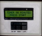
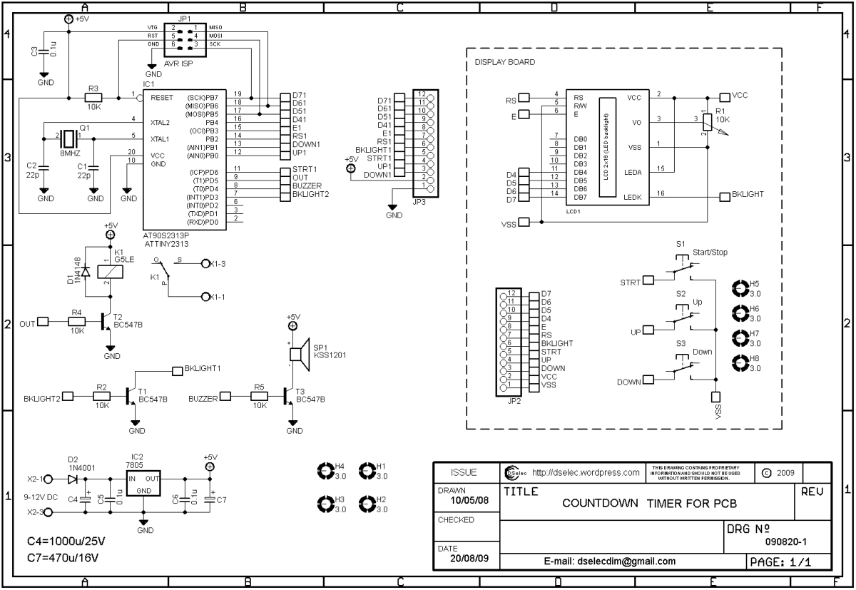
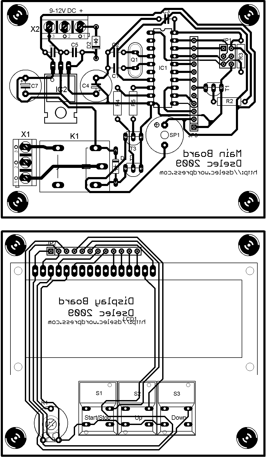
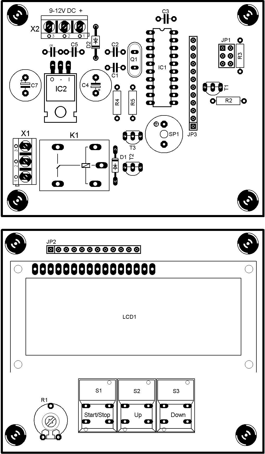
This is a countdown counter based on ATtiny2313, primary developed for my PCB exposure box, but it can be used for other purposes too. The counting range is between 1 and 90 minutes and it can be adjusted with up or down buttons (high and low in the pictures). After the desired time is set, the countdown starts by pressing the start/stop button (on/off in the pictures). By pressing the same button we can interrupt the counting at any time we want. After the count expires we hear a beeping sound and the load is disconnected. By pressing start/stop button we reset the counter and we are ready for another lap. All actions included the time remaining are shown in the LCD display. The schematic is shown here: And the PCB:
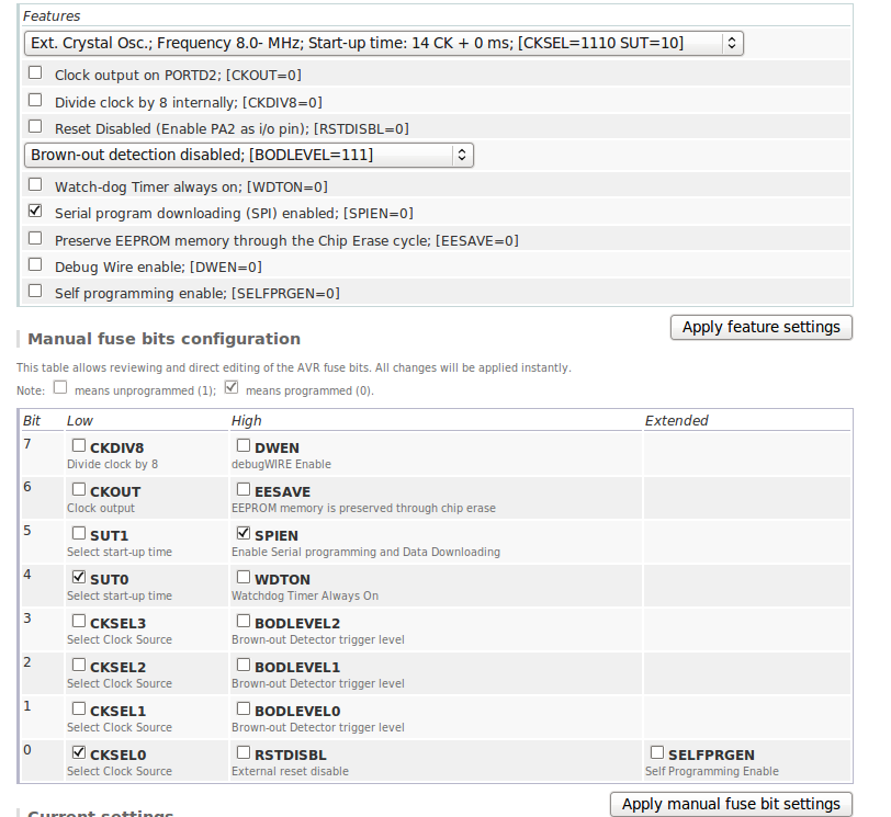
Click on the images to get larger view. The timer was originally build using the AT90S2313 but is obsolete now. Anyway the ATtiny2313 and AT90S2313 are pin to pin compatible and you can use it if you have it. The code for the micro was developed using BASCOM-AVR. Download the source code and the hex file from here: Source code: HEX file: The schematic and pcb was made with Cadsoft’s eagle. Download the .sch and .brd files from here: .sch file: .brd file: You can program the ATtiny2313 on board by using the 6-pin header which is compatible with the 6-pin header of STK-500. If you use STK-500 to program the micro you have to remove the VTARGET jumper first or the STK-500 will be damaged. The ATtiny2313 is shipped with internal oscillator selected by default, so you have to program the appropriate fuses by yourself. Use the on-line AVR Fuse Calculator and set the settings for the fuses (see the photo, click to get a larger view). Important! A bug found in the placement of transistors T1, T2, T3 in PCB. if you have any questions submit a comment or send e-mail: dselecdim at gmail dot com |
-
Subscribe
Subscribed
Already have a WordPress.com account? Log in now.


sir,
can you email to me the original picture of kompenan pcb time control.
tq
Hi there
Is it possible to the the PCB layout in a PDF file ? Then it will be possible to print it out in scale 1:1 – to make sure, that things align correctly
/bi
sir can i have the 1:1 scale of the circuit design? just email it to me.. tnx..
[…] Atmel ATtiny2313 dayalı PCB pozlama geri sayım […]